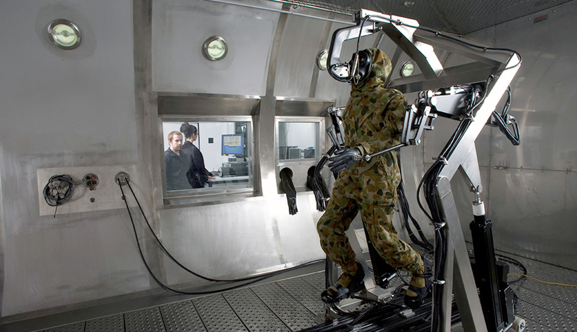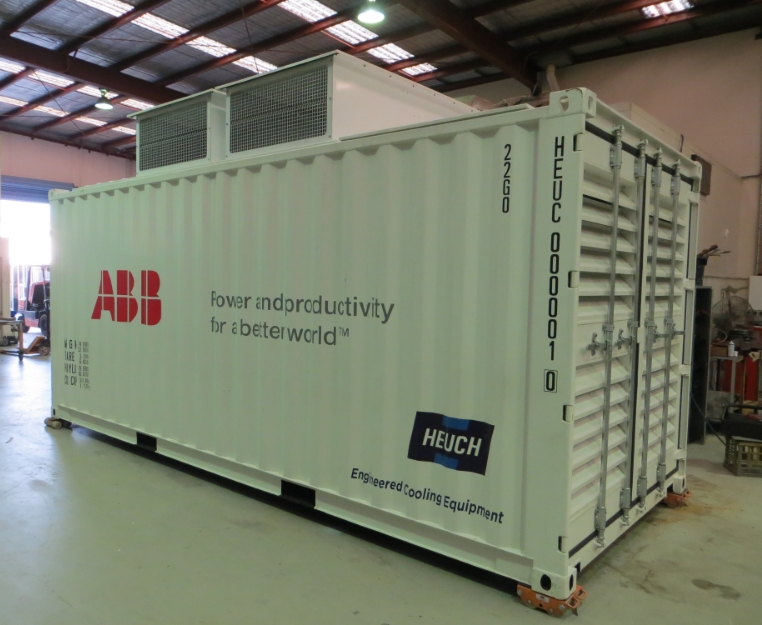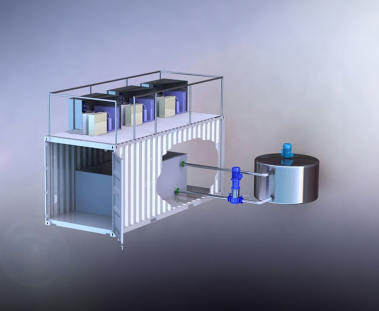

This Environmental Test Chamber & associated equipment was designed, constructed, installed & commissioned by Heuch. The Environmental Test Chamber was featured in a segment of ABC’s Catalyst program, presenting the Chambers use as a testing environment for Australian Defence Force uniforms.
To view the video and read the story transcript please click here.
The functional areas of the Facility are as follows:
The cooling system is designed for efficiency, simplicity & stability. The greenhouse & water requirement profile is minimized by the selected use of two separate air-cooled, high & low temperature refrigerant/compressor systems within a single chiller unit to maintain the operational conditions required.
The set point temperature of the cooling brine is manipulated by the Chamber PLC system to suit the desired operational set point. The PLC has the capacity to drive the control set point to provide for rapid changes in set point temperatures upon demand & then soften the differential as the control point is reached for a close approach temperature.
A large internal brine fluid buffer tank provides for high levels of energy efficiency & control stability. The twin refrigeration compressor circuits include multi-stage capacity control, brine circulation pump, operational & safety functions.
A variable temperature recirculating Brine system (ethylene glycol) provides heating fluid to a large internal stainless steel air-brine heat exchanger. The heated brine temperature is manipulated by the PLC system to provide for very close approach temperatures to the Chamber operational set point.
A mains water, electric cathode, steam humidifier provides humidification whenever the chamber is above +4°C. The unit offers variable steam generation from 0% to 100% of its rated capacity. Filtered mains water is electrically heated & distributed into the chamber plant space by a self draining, heated stainless steel distribution wand.
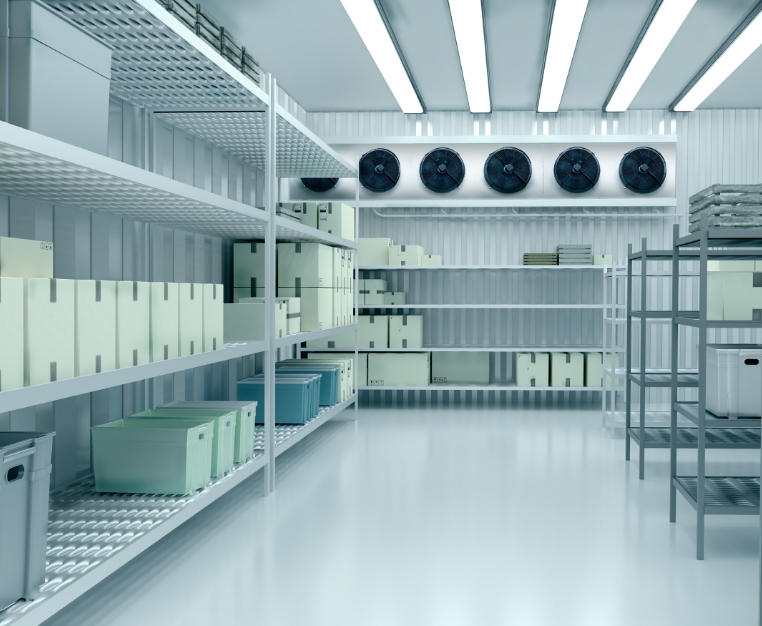
External, variable speed motors are direct coupled to two stainless steel, backward curved centrifugal fans within the Chamber plant area. Two variable speed Fans are dedicated to the movement of re-circulated air around the Chamber to generally maintain the required chamber velocity or temperature gradient in accordance with the demands of the PLC.
The third Fan is used to move a side stream of air across the internal air-brine heat exchangers where its constituent nature is adjusted to meet the temperature &/or humidity requirements of the Chamber space.
A polished , stainless steel ceiling & heavy-duty floor grid provides for an even, top to bottom, distribution of the air stream within the Chamber operational space.
The Chamber can be pressurized during testing & this allows the Chamber to operate across the full environmental application range.
The Chamber can be operated at a negative pressure between -1.0 Pa & -60 Pa during experimentation to allow for the positive containment of stimulants & decontaminants applied within the Chamber.
A 1600 litre HDPE water storage tank & pump system is connected to the Chamber & Air Lock by a stainless steel distribution system. The distribution system supplies a series of stainless steel spray balls to provide for wash down of the internal chamber surfaces.
Condensate & waste from the deluge system is collected into the Chamber sump where it is pumped to a remote 6000 liter HDPE effluent storage tank for later treatment & removal by others as required.
The purged air is drawn through the Chamber & the resultant exhaust air is vented through the series of manually selected air scrubbing components before finally venting to the external exhaust stack.
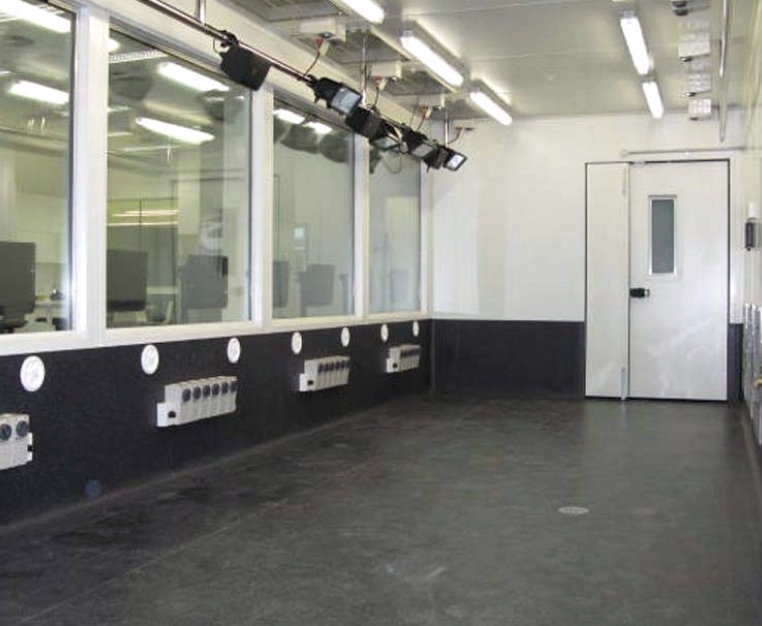
An Innotech GenII series PLC touch-panel control system provides the operator with the tools to perform a wide variety of experimental tests within an enclosed, repeatable environment. The user friendly touch screen, within the adjacent control room, includes a graphical display of the system with a selection of menu activities & control set points.
The PLC system automatically co-ordinates the activities of a variety of air control valves, ventilation fans & primary cooling/heating components.